Showing posts with label SMT technology. Show all posts

Sunday, December 31, 2017

JUKI KD775 E93128020A0 L Pressure S.V. Cable ASM

JUKI KD775 E93128020A0 L Pressure S.V. Cable ASM 


E93128020A0 L PRESSURE S

E93158020A0 C PRESSURE S

E93188020A0 R PRESSURE S


E93188020B0   R PRESSURE S.V ASM. 1

E93128020B0   L PRESSURE S.V ASM. 1

E93158020B0   C PRESSURE S.V ASM. 1

PX055201000   MUFFLER (PLASTIC) 1

PX055201000   MUFFLER (PLASTIC) 1

PX055201000   MUFFLER (PLASTIC) 1

E30448020A0   CONNECTOR BLOCK ASM. 3

E30188020A0   HEAD MAIN BUSH ASM. 3

E2330725000   CABLE BEARER ASM. 1

E93148020B0   PRESSURE SENSOR ASM. 1

E93208020B0   PRESSURE SENSOR ASM. 1

E93178020B0   PRESSURE SENSOR ASM. 1

Thursday, December 7, 2017

Optimization case of abreast smt nozzle style placement machine

Optimization case of abreast smt nozzle style placement machine 

1.SMT Feeder position considerations: For abreast nozzle of placement machine feeder position is slightly different from the turret style,
The arrangement principle is as follows:

(1) The classification is based on components, the same type of components is arranged together, as far as possible to achieve simultaneous sampling. Side-by-side nozzle, between the two nozzles have a fixed distance (such as GSM is 20mm width), this distance is just with the station 8 mm feeder is equal, in order to save the picking time, the best way is to patch the first nozzle at the same time to absorb the components, such as less than 12 mm components are arranged together, 16 mm components are arranged together, greater than 20mm Of the components are arranged together.

(2) The same type of components placed in the order on the feeder, should first place the most components of the number of components, followed by the placement of a relatively large number of components, and finally placed fewer components components. Components placed as much as possible to patch position The placement of the material and the placement of the total travel the shortest principle, such as the placement of the location of the central part of the board, the feeder position is preferentially installed in the middle of the printed circuit board near the middle of the station, you can save the head back and forth moving time. In addition, for the board to install a larger number of components, in order to save time to pick up a feeder can be changed to a number of feeder, while picking, while the same time, Extend the refueling time, save machine downtime.

(3) it will be placed in the placement of the components are not far apart, the placement of the patch to reduce the moving distance.

2. Programming considerations.
(1) Minimize the number of nozzle replacements. The components are arranged in the same type, and the nozzle can draw such components at the same time. When the type of suction nozzle is completed, replace the next nozzle type and avoid frequent replacement of the nozzle. When more than one make-up placement programming, you can make the puzzle expansion as a whole board placement, reduce the number of nozzle replacement.

(2) To reduce the loading and unloading head before and after the material to move back and forth distance in the element reclaiming material, as far as possible in the machine for a feeding platform for material, such as only in the back of the material station to take, to avoid before and after the material caused by the increase in moving time .

(3) To Consider the ccd camera ,and the general placement machine has two sets of cameras, the first group installed in the patch head, the components picked up, the patch head in the process of moving to complete the flight identification to the middle of time, The camera is usually handled with components smaller than a certain size, for example, less than 20mm. The second group is mounted on a part of the machine and the suction nozzle picks up the components and needs to be identified on the camera. This will take part of the movement time , Usually this type of camera to identify the larger high-precision components, such as more than 20mm components. In programming, try to make multiple nozzles to pick up, identify and mount at the same time as far as possible not to absorb the need for two kinds of camera identification components , To spend more time to identify the entire placement of the head to wait for all the nozzle to complete, to absorb the next set of components.

(4) Tray discs to consider. General multi-function machines, all with a number of waffle Tray disk. Mounter is usually a Tray disk to move to the patch picking position, after drawing components, and then replace another Tray disk , Because Tray mobile replacement speed is slower than the placement speed, multi-nozzle side by side patch, if the adsorption components did not reach all, need to wait for the arrival of the next Tray disk components, so a waste of time. Programming should be considered, in the replacement Tray Disk time, patch head do not have to wait, to install other components, and then go to absorb  ic tray components.

Monday, December 4, 2017

The similarities and differences of solder wire and silver-free solder wir

The similarities and differences of solder wire and silver-free solder wire 

(1) the melting point is different: due to the different metal alloy, so the melting point is also different. Silver-free lead-free solder wire melting point: 217 degrees, and lead-free solder wire melting point: 227 degrees difference of about 10 degrees.


(2) different metal composition: silver-free lead-free solder wire is made of tin silver copper alloy, and lead-free solder wire is a tin and copper alloy composition, excluding silver metal composition.


(3) Costs are different: silver-free lead-free solder wire is more expensive than lead-free solder wire because of the high price of silver metal. This is the biggest advantage of lead-free solder wire. The higher the cost, the more expensive the cost

 The similarities and differences of solder wire and silver-free solder wire

(4) the overall performance of different: due to the role of silver metal, lead-free solder wire than lead-free solder wire firmness better, stronger, more solid solder joints.Second, the conductive properties in the solder joint is also very important , Silver is a very good conductive metal, so silver-free lead-free solder wire than lead-free solder wire conductivity, thermal conductivity and so on are better. These properties are lead-free solder wire can not go beyond.


(5) solder color gloss different: lead-free solder wire gloss is showing a certain degree of brightness, look better look. This is one of the advantages of lead-free solder wire, but the solder color does not mean the welding Point of its own welding performance, while the silver-free lead-free solder wire solder joints affect the appearance of the solder color brightness of the color.As the silver metal is matte metal, not bright metal, so silver-free solder wire solder Point gloss is matte color and brightless.

The key process of SMT reflow welding rework technology

The key process of SMT reflow welding rework technology 

Reflow before the appropriate preheating PCB board; re-flow after the rapid cooling of the solder joints. Two of the most critical processes for the successful repair of SMT are also the two most likely to overlook the problem:
Since these two basic processes are often overlooked by the repair technician, in fact, sometimes the repair is worse than the situation before the repair. Although some "rework"defects can sometimes be found by the post-process inspector, but in most cases always do not see, but in the future circuit test will soon be exposed.Preheat - Prerequisites for successful rework.


It is true that PCB processing at high temperatures (315-426 ° C) for a long time poses a lot of potential problems. Heat damage, such as pad and lead warping, substrate delamination, raw white spots or blistering, discoloration. Board Alice and Burning are usually caused by the inspector's attention. However, it is precisely because it will not "burn bad plate" does not mean that "plate is not damaged." High temperature on the PCB "invisible" damage even more serious than the above list of problems. For decades, numerous tests have repeatedly demonstrated that PCBs and their components can "pass" rework after the test and test, the decay rate higher than the normal PCB board. This kind of substrate warpage and its circuit element attenuation and other "stealth" problem comes from different materials of different expansion coefficient. Obviously, these problems will not be self-exposed, even in the beginning of the circuit test was not found, but still lurking in the PCB components.

Although the "repair" looks good, but as people often say a word: "surgery is successful, but the patient unfortunately died."Due to the large thermal stress, the PCB assembly at room temperature (21 ° C) has a temperature difference of about 349 ° C for the circuit board and its components when it is exposed to a hot iron with a heat source of about 370 ° C, a welding tool or a hot head. Variety,Produce "popcorn" phenomenon."Popcorn" phenomenon refers to the existence of an integrated circuit or SMD in the device inside the moisture in the repair process of rapid heat, so that moisture expansion,the phenomenon of micro-burst or rupture. 

Therefore, the semiconductor industry and circuit board manufacturing industry requires production staff in the reflow before, as far as possible to shorten the warm-up time,quickly rose to reflow temperature. In fact, the preheating stage of the PCB assembly reflow process has been included. Regardless of PCB assembly plant is the use of wave soldering, infrared vapor phase or convection reflow, each method are generally preheated or heat treatment, the temperature is generally 140-160 ℃. In the implementation of reflow before the use of a simple short-term preheating PCB can solve many problems when the repair. This has been in the reflow process has been a few years of successful history.the benefits of preheating the PCB assembly before reflowing are multifaceted.Since the preheating of the plate reduces the reflow temperature, both wave soldering, IR / vapor welding and convection reflow can be performed at about 260 ° C.The benefits of preheating are multifaceted and integrated. First, preheating or "heat-treating" components prior to commencing reflow helps to activate the flux, remove the oxides and surface films of the surface to be welded, and the volatiles of the flux itself. Accordingly, this cleaning of the flux prior to reflow will enhance the wetting effect. Preheating is to heat the entire assembly below the melting point of the solder and the temperature of the reflow. This can greatly reduce the risk of thermal shock to the substrate and its components. Otherwise rapid heating will increase the temperature gradient within the assembly and produce thermal shock. The large temperature gradient generated inside the assembly will form thermomechanical stresses that cause the material with low thermal expansion to be brittle, causing rupture and damage. SMT chip resistors and capacitors are particularly susceptible to thermal shock.

In addition, if the entire assembly is preheated, the reflow temperature and the reflow time can be reduced. If there is no preheating, the only way to only further increase the reflow temperature, or extend the reflow time, no matter which way is not appropriate, should be avoided.Reduced rework makes the board more reliable.As a benchmark for welding temperature, the use of different welding methods, welding temperature is not the same, for example: Most of the wave soldering temperature of about 240-260 ℃, steam welding temperature of about 215 ℃, reflow temperature of about 230 ℃. To be fair, the rework temperature is not higher than the reflow temperature. Although the temperature is close, it is never possible to achieve the same temperature. This is because all the rework processes require only one local component to be heated, and the reflow requires the entire PCB assembly to be heated, both for wave soldering and vapor phase reflow.

Another factor limiting the reduction in reflow temperatures in rework is the industry standard, which means that the temperature of the components around the repair point must never exceed 170 ° C. Therefore, the reflow temperature in the reflow should be with the PCB component itself and to reflow the size of the components to adapt to the size of the PCB board is essentially due to the local rework, so the repair process limits the PCB board maintenance temperature. The temperature range of the localized rework is higher than the temperature in the production process to counteract the endotherm of the entire board assembly.

In this case, there is no good reason to say that the repair temperature of the entire board can not be higher than the reflow temperature in the production process, thus approaching the target temperature recommended by the semiconductor manufacturer.Three methods of preheating PCB components before repair or repair:Today, preheating PCB components are divided into three categories: oven, hot plate and hot air tank. It is effective to use an oven to preheat the substrate before reworking and reflow the components. Moreover, the use of baking is a favorable way to preheat the oven in baking out some of the internal circuits in the internal moisture and prevent the popcorn phenomenon. The so-called popcorn phenomenon refers to the repair of the SMD device in the humidity above the normal device humidity suddenly in the rapid warming will occur when the micro-crack. PCB in the preheating oven baking time is longer,Generally up to 8 hours or so.

One of the drawbacks of the preheating oven is that it is different from the hot plate and the hot air tank, and it is not possible to preheat by a technician and to rework it at the same time. Moreover, it is impossible to quickly cool the solder joint in the oven.Hot plate is the most ineffective way to preheat PCB board. Because the PCB components to repair is not all single-sided,Today is the world of hybrid technology, one side is all flat or flat PCB components is indeed rare. PCB on both sides of the substrate are generally installed components. It is not possible for these uneven surfaces to be preheated with hot plates.The second drawback of the hot plate is that once the solder reflows, the hot plate will continue to release heat to the PCB assembly. This is because, even after unplugging the power supply, there will still be stored residual heat in the hot plate to continue to conduct the PCB to prevent the solder joint cooling rate. This obstruction of solder joints can cause unnecessary lead precipitation to form a lead bath, reducing the solder joint strength and deteriorating.

The advantage of using a hot air tank to preheat is that the hot air tank does not take into account the shape (and bottom structure) of the PCB assembly, and the hot air can enter the corners of the PCB assembly directly and quickly. So that the entire PCB assembly heating evenly,And shorten the heating time.Secondary cooling of solder joint in PCB assembly

As mentioned earlier, the challenge of SMT to PCBA (PCB components) is that the repair process should mimic the production process. Facts have proved:
First, preheating the PCB assembly before reflow is necessary for the successful production of the PCBA; secondly, it is also important to quickly cool the components immediately after reflow. And these two simple craft has been ignored by people. However, in the through-hole technology and micro-welding of sensitive components, preheating and secondary cooling is even more important.

Common reflow equipment such as chain furnace, PCB components through the re-flow zone immediately after entering the cooling zone. With the PCB assembly into the cooling zone, in order to achieve rapid cooling,ventilation of PCB components is very important, the general repair and production equipment itself is integrated.The slow cooling of the PCB assembly after recirculation causes the unwanted lead-filled liquid pool in the liquid solder to reduce the solder joint strength. However, the use of rapid cooling can prevent the precipitation of lead, so that the grain structure is more tight, more solid solder joints.In addition, the faster cooling of the solder joint reduces the quality of the PCB assembly due to accidental movement or vibration during reflow. For production and rework, it is another advantage of the secondary cooling of the PCB assembly by reducing the possible misalignment and tombstone of small SMD.

Summary:
There are many benefits of secondary cooling PCB components when properly warmed up and reflowed, and these two simple procedures need to be included in the technician's rework. In fact, when preheating the PCB, the technician can do other preparatory work at the same time, such as solder paste and flux on the PCB.Of course, the need to solve the problem of new refurbished PCB component process, because it has not passed the circuit test, which is a real time to save. Obviously, there is no need to repair the PCB in the repair and save the cost.

A Practical Guide to Achieving Lead-Free Electronics Assembly

A Practical Guide to Achieving Lead-Free Electronics Assembly


To successfully achieve lead-free electronics assembly, each participant in the manufacturing process, from purchasing to engineering to maintenance to Quality/Inspection, must have a solid understanding of the changes required of them. This pertains to considerations regarding design, components, PWBs, solder alloys, fluxe s, printing, reflow, wave soldering, rework, cleaning, equipment wear & tear and inspection.


With the WEEE and RoHS Directive in Europe (in its most recent revision) potentially outlawing lead from electronics produced and imported in the EU as early as 2006 and foreign competition driving the implementation of lead-free electronics assembly around the world, additional questions regarding how manufacturers can successfully transition to lead-free assembly continue to arise.

A great deal of consortia work and empirical data exists on lead-free soldering. What has been lacking, however, are studies directly related to real-world applications and advice on such topics as procurement, design, processes, maintenance, inspection, etc. This paper shall address each step of the manufacturing cycle and discuss the means to overcome the many challenges of lead-free assembly.


Purchasing’s main challenge is to requisition components and PWBs suitable for lead-free assembly and to balance the needs for parts with the myriad of lead finish, PWB surface finish and solder alloys currently available.

Although vendors are offering some components with lead-free lead finishes such tin, Pd/Ni, Au/Ni, and Pd/Au/Ni, purchasing will be far more restricted in terms of part availability than in the past. When attempting to purchase lead-free components, one may run into several obstacles: only a single-source for a part, a part that is not quite suitable, a change in lead-times, significantly more expensive, or no source at all. To overcome these obstacles, Purchasing needs to work in close conjunction with Engineering/Design

and vendors to ensure that the lead-free parts needed are available and compatible with the manufacturing process.

As with components, there is some availability of lead-free PWB surface finishes . OSPs, Au/Ni, Immersion Sn, Ag, and Lead-Free HAL finish PWBs have been on the market for some time now. Again, Purchasing needs to work in close conjunction with Engineering/Design and vendors to ensure that the lead-free parts needed are available compatible with the manufacturing process.

Materials Management

The many component and PWB coatings, as well as several possible solder alloys results in a huge matrix of potential material intermix, and clearly can complicate materials management. More than ever, purchasing will need to be attuned to which parts go with which product. Once again, Purchasing must work in close conjunction with Engineering to ensure that ordering is streamlined and that the appropriate parts are available for particular jobs.

Engineering

The switch to lead-free assembly affects virtually all aspects of the Engineering function. Engineering personnel will have to pay close attention to design, components, PWBs, solder alloys, fluxes, and the printing, reflow, wave soldering, rework and cleaning processes and equipment.

Design

Established PCB-design rules may need to change during the transition to lead-free soldering. Currently, industry guidelines govern component lead-pad and land size, track width and spacing, via and through-hole dimensions, and similar factors to ensure manufacturability and reliability. However, the physical characteristics of any solder include subtle factors, such as its ductility and elasticity. In addition, the local heating of component leads and their pads causes some thermal expansion during operation, which tin -lead solder accommodates and matches.

In determining design solutions, Design should try to remain with as many standard parts as possible. This will reduce the unpredictability encountered with atypical parts. In addition, if the assembly is designed to have a long life, factor in the reduced moisture resistance of parts. Furthermore, Design must factor in the higher temperatures required for connectors .

Material Considerations

The first critical duty is to ensure that the parts to be used will be compatible and reliable for their particular application. Compatibility relates to components , PWBs , solder alloy and flux. Reliability relates to component concerns, which includes such factors as Moisture Sensitivity Level (MSL) Rating, wetting and tin whiskering.

Component Reliability Concerns

The higher melting temperatures of the lead-free solders that are coming into use mandate components that can withstand the increased temperature stresses of the soldering process. Life -test data for many components at these higher temperatures is less comprehensive than it is for tin/lead processes. To maximize reliability, Engineering should start looking now at all critical components, design rules, fabrication processes, component engineering, and reliability records.

A critical factor in the transition to lead-free assembly is the MSL rating of components. To date, industry testing has demonstrated that there is no generic solution for maintaining an IC’s MSL with a higher reflow profile. However, it has been demonstrated that degradation of MSL may increase with increasing profile dwell above 200°C and that MSL typically degrades by one level for every 5 to 10°C increase of peak reflow temperature. Therefore, all ICs must be reclassified for lead-free applications and the impact to MSL. This could result in an increased need to pre -bake parts and more stringent storage methods.

As discussed above, several lead-free component lead finishes are available. It should be noted that these different materials have different wetting characteristics and that Engineering should consider wetting when specifying components. Engineering also needs to balance the fact that increased reflow temperatures can improve wetting, but worsen reliability. In addition, Design should be aware of reduced solderability on second-side reflow and through-hole processes.

Another hot topic of discussion is tin whiskering, which continues to be an oft -misunderstood and debated subject. Proponents of matte tin argue that whiskering is a result of the plating process, and not necessarily inherent to pure tin. They demonstrate that whiskering can also occur with Sn/Bi, etc. Others, however, suggest that a dopant is needed to aebate and studies regarding this topic, work closely with component vendors and participate in studies to determine the most suitable lead finish for their applications.

PWBs

Several PWB lead-free surface finish options exist. Many of these, such as OSPs and Au/Ni, have been available for years. Engineering should determine the finish of choice based upon wetting, storage, planarity and cost issues. In addition, it must be ensured that board materials can withstand reflow temperatures without warpage or other damage. For many cases, FR-4 will remain acceptable, but other applications may require a modification.

Solder Alloy and Flux

Unfortunately, despite a great deal of research, comprehensive and comparative data on lead-free alloys is lacking. The list of solder alloy requirements is lengthy and involved. In general, technical requirements include being non-“hazardous”, mechanically reliable, thermal fatigue resistant, good wetting, relatively low melt ing temperature and compatible with a variety of lead-bearing and lead-free surface coatings. In addition, one must consider logistical issues such as alloy cost, availability and patent issues. While most of the world has settled on the tin -silver-family of alloys, a good deal of debate still exists as to which exact composition is ideal, and of course others will choose alloys from outside of this family. As with all other technical issues, although there has been much consortia work on alloy selection, the alloy of choice will come down to the specific requirements of each unique assembly. Your choice of alloy is dependent upon your application and should be proven out to your standards.

As with alloys, what is a suitable flux (paste, liquid flux and cored wire) for one manufacturer may not be for another. Select flux chemistries suitable for lead-free processing and your particular application. One should consider a flux’s activation temperature, activity level, compatibility with chosen alloy and reliability properties such as SIR, electromigration.

Process Considerations

Once it is confirmed that the parts and materials to be used in lead-free assembly are available, suitable and reliable, it is time to get the processes optimized in order to achieve maximum throughput and reliability. To do so, Engineering must refocus attention to paste handling, printing, reflow, wave soldering, rework & repair and cleaning.

Paste Handling

Shelf-lives with lead-free pastes may be reduced as compared to tin/lead, and storage conditions may be slightly more stringent. However, in general, the same rules as with tin/lead apply. For example, prevent/minimize paste’s exposure to heat and humidity, allo w paste to come to room temp erature before using and do not mix old and new paste in the same jar. If one follows proper paste handling procedures now and has good results from these, there should be very few issues when transitioning to lead-free paste use.

Printing

In general, no major changes to the printing process should be necessary. That is, lead-free pastes should exhibit similar features on the stencil and the same equipment set points should transition well. One can expect similar performance in terms of stencil life, aperture release, print definition, high-speed print capabilities, print repeatability, etc. However, this depends on the paste manufacturer and if they have density issues resolved. If one experiences a significant difference in printing a lead-free solder paste versus the equivalent tin/lead paste, it may be related to the metal loading or flux chemistry of the paste in

use. In this case, Engineering should work with the paste vendor, or try competitive pastes, in order to resolve these issues.

As tin/lead solder alloys tend to have better wetting than most lead-free alloys, some stencil design modifications may be needed to maximize spread of paste and counteract inferior wetting. Engineers should run tests with lead-free alloys on their current stencils to confirm adequate spread and wetting. If wetting is not sufficient and cannot be rectified by other means, stencil design modifications may be in order.


Reflow

This is the SMT process area that will be most affected by a switch to lead-free processing. Most lead-free alloys require higher reflow temperatures than the 210-220°C peak temperature of tin/lead; anywhere from 235-260°C is common. This higher reflow temperature dictates that one should minimize ? T and maximize wetting through the reflow profile (including cooling), and could possibly mandate reflow equipment changes .

Profile - Depending upon the oven utilized and the density of the assembly being processed, the Ramp -to-Spike process is generally recommended for lead-free assembly. This profile offers superior wetting and less thermal exposure than the traditional Ramp -Soak-Spike profile .

Depending upon the alloy selected, wave soldering will require a pot temperature of 260-275°C. This increase of temperature and the change in solder alloy will require some additional process changes.

Flux- May require a change in liquid fluxes to compensate for the poor wetting of some alloys and high thermal stresses of the wave process. If changing fluxes, particular attention should be paid to both to operating window it offers and the material’s reliability characteristics.

Equipment- Most modern wave solder machines can provide the necessary heat (preheat and wave) for lead-free soldering. However, as shown in figures 3 and 41, the high-tin lead-free alloys rapidly dissolve the materials often used in wave solder equipment. Stainless steel pots, nozzles, impellers and other parts will need to be replaced with cast iron and other materials available from wave soldering equipment manufacturers or be covered with an appropriate paint that should protect the parts for 2-3 years. In addition, a nitrogen blanket may be required, depending upon the alloy and flux selected.

Rework and Repair

Materials - Operators must be re-trained for lead-free rework, as the lead-free solders do not flow as well as tin/lead. This could also require stronger cored wire fluxes to be used. As with any change of flux chemistry, if changing wire solders, particular attention should be paid to both to operating window it offers and the material’s reliability characteristics. Some wires often assumed to be safe to leave uncleaned are actually classified as rosin fully -activated and could cause field failures .

All rework should use the same lead-free solder alloy as originally used on the solder joint; different lead-free solder formulations should not be mixed on the same joint. If more than one alloy is in use in the production process (i.e., Sn/Ag/Cu for SMT and Sn/Cu for wave soldering), operators should be trained to use the correct wire for each part . For this reason alone, it is advisable to use a single solder alloy for all assembly operations.

Equipment- It is necessary to ensure that the desoldering and soldering stations are suitable for lead-free processing, i.e. can reach the necessary temperatures for lead-free soldering. It should be noted that lead-free soldering can wear out tips at a much higher rate than tin/lead.

Cleaning

In general, studies have demonstrated that post-process flux residues from lead-free applications are still cleanable. Water soluble chemistries may be cleaned in water, no-clean and RMA chemistries with a saponifier or cleaning solvent. However, it has been found that an increase in pressure, cleaning times and/or cleaner concentrations often is necessary. The efficiency of the cleaning equipment, strength of the cleaner, melting point of the alloy being used and thermal stability and propensity of the flux to “char” all affect the cleanability of an assembly.

urrent test fixture settings could possibly damage lead-free solder joints. In addition, the higher reflow temperatures may result in charring and make probing through “pin probeable” flux residues more difficult. This could warrant changing flux chemistries or even residue removal in some cases.

Solder Paste Printing – the Most Critical Part of Building a Quality PCB Explained

Solder Paste Printing – the Most Critical Part of Building a Quality PCB Explained

If someone were to ask what the most important part of their favorite electronic device is, they are likely to point to the printed circuit board (PCB) responsible for making the device work before moving on to other components. From large motherboards to tiny chips, most of the technology that retail consumers take for granted comes down to a properly installed and calibrated PCB.

While there are a great deal of steps in the PCB assembly process, and each is extreme importance, one stands out among all the others as being the most critical for ensuring lasting success. Incorporating surface‐mounted devices (SMDs) onto PCBS is the most critical part of a building a quality electronics product, and for good reason.

Attaching Devices to PCBs – Solder Paste Printing

One of the most popular and reliable ways to attach SMDs to boards is using a process called solder paste printing. Essentially, a screen printing device uses a stencil of the finished boards components to apply solder paste to the board with extreme precision.

Solder paste is exactly what it sounds like – a blended mix of flux medium and graded particles of solder powder. It serves as the attachment medium between the device's interconnection sites and the PCB itself.

After a PCB has solder paste accurately layered over it, PCB assemblers can reflow the solder paste – melt it at a specific temperature – to form a tight, conductive bond.

In many ways, this process is similar to screen printing graphics or designs onto textiles. The main difference is the level of precision required – both the amount and consistency of the solder paste must adhere to strictly observed standards in order to create a durable bond.

Facing Challenges with Solder Paste Printing PCBs

There are many challenges to consistently solder paste printing PCBs. Less‐than‐professional PCB assembly companies will often introduce errors during this delicate process – especially when rushing to complete large orders with tight deadlines.

In order for the process to be successful, PCB assemblers must respect several principles:

Create a Perfect Stencil: The accuracy of the process depends on the accuracy of the stencil. A shoddy, imprecise, or poorly printed stencil will never produce reliable results.

Program the Screen Printer Properly: Solder paste screen printing devices need exact measurements and calibration to perform their work with precision. Expert screen printing programming is a valuable skill in the PCB industry.

Apply the Right Amount of Solder Paste: Too much solder paste will create an imperfect outline, while a lack of solder paste will prevent the SMDs from sticking.

Choose the Right Process: There are two main methods to achieving a good print – mesh screen printing and metal screen printing. While the former is the cheapest method, it does not work on small SMDs that require precision attachment.

By paying close attention the solder paste printing process, you can accurately gauge just how capable a PCB assembly company truly is. Think of this process as the tell‐tale sign of a professional approach.

JUKI NF ATF CTF FTF series smt feeder of applicable models and differences?|Juki feeder feature

JUKI  NF ATF CTF FTF series smt feeder of applicable models and differences?|Juki feeder feature


1.NF12, NF16, NF32, NF44, NF56, NF56 is mainly used for the processing of JUKI KE730 KE740 KE750 KE760 placement machine.


2. JUKI ATF feeder is Japan's JUKI manufacturers for KE2070 high-speed placement machine research and development of the new feeder.
As this kind of feeder is easily to use, can be achieved non-stop refueling, waste plastic tape and tape without the need to automatically pulley into the waste box.
ATF feeder launched early there have been frequent cassette phenomenon, waste plastic belt can not be properly exported.
JUKI company to improve this problem, and now the market's ATF feeder has been completely solve the cassette problems.
ATF fly up to AF03HP, AF05HP, AF081E, AF081P and other models.
At present ATF feeder has been developed to AF32MM.


3.JUKI CTF feeder is JUKI company based on KE2050 KE2060 and FX-1 medium speed machine developed the old feeder.
The feeder use convenience, waste plastic belt through the reel tape, tape is automatically drooping into the waste box.
CTF is now the market share of the highest feeder, good reputation and stable quality.
CTF fly up to CF03HP paste 0201 components;
CF05HP is 8 * 2 posted 0402 of the material;
CF081E, CF081P is posted 0603 material.
Now JUKI manufacturer launched CTF upgrade section CTFR.


                                  JUKI CF series feeder


4.TCF feeder is JUKI company from 12MM (including 12MM) above all mechanical feeder collectively.
At present the domestic market is almost all large FTF models. which feeder also because of the stability of the quality of the customer to win a very good reputation.

                        JUKI FF series feeder

What's the price of the SMT placement machine?

What's the price of the SMT placement machine?

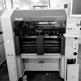
PCB Placement machine is the most important equipment in SMT line, the SMT machine 's cost is the total 70% production lines, to achieve high speed and precision automatic placement of components of the equipment, is the most important and complex equipment of the production of SMT. The automatic placement machine is the main equipment in the SMT production line. The automatic placement machine has been developed from the early low speed mechanical Mounter to the high-speed optical alignment
Placement machine, and to multi-functional, flexible connection modular development. At present, foreign SMT machine has SONY, SONY (Japan),
Assembleon Anbiang, Siemens SIEMENS (Germany), Panasonic (Japan), Matsushita (Japan), FUJI Fuji YAMAHA YAMAHA (Japan), JUKI (Japan), MIRAE (Korea), SAMSUNG Samsung (Korea),  global UNIVERSAL (United States)


Other brands, from looking at the past 10 years, SMT abroad continued to control the market and voice of high-end machine absolutely, the price has been high, Japan has been considerable advantages in the field of machine technology, this is because the Japanese have a very good industrial base and technical accumulation, especially servo motor, high precision guide screw, excellent quality is complete, the short term Chinese domestic manufacturers is difficult to have a big breakthrough, many manufacturers will buy new original machine, including Fuji, Matsushita, SIEMENS's most expensive, ultra high speed machine more than 1 million very common, but for some small and medium-sized circuit board manufacturers, large one-time investment is risky, some of the original second-hand machine can meet the requirements, to provide these small manufacturers a very high price solution Resolution!
High cost secondary placement machine has the following brands (prices according to the number of years and maintenance changes, some brands for reference):
Samsung Samsung Mounter: Samsung CP45:USD12000, CP45FV-NEO price: USD14000, SM421 price: USD30000, SM411 price: USD35000;
YS12 price of YAMAHA YAMAHA, Japan: USD50000-80000;
Japan heavy machine JUKI:2070 price: USD30000-50000; 2080 price: USD40000-90000;
The price of the mobile placement machine is also different according to their application, and the price difference is also compared
In addition, the automatic placement machine is the earliest to foreign automatic placement machine based. The price differentials of these brands are also relatively large. In recent years, the domestic placement machine development is relatively fast, the domestic automatic placement machine brand is also
More, the price difference is also relatively large. Automatic placement machine how much money? The following will be explained by the Beijing British science and technology mounter
The amount of automatic Mounter depends mainly on the following factors.

1, automatic placement machine, how much money to distinguish between domestic or imported mounter?.
Automatic placement machine prices on the whole, imports of automatic placement machine and domestic automatic placement machine has several times the gap, the low-end domestic automatic placement machine in general
About one hundred thousand, high-speed domestic automatic placement machine is generally less than six hundred thousand. Imported automatic placement machine is low-end automatic placement machine, also more automatic than domestic high-speed paste
The price of the film machine is much higher, if it is a high-speed machine, usually USD150000-USD250000.

2, the quality of the automatic placement machine also determines the price of the automatic placement machine:
The quality of the product is closely related to the price, whether it is an automatic placement machine or an automatic placement machine imported
Materials and accessories are made of high quality materials, in addition to quality assurance, then its price is naturally more expensive.


3, automatic placement machine operating mode is different, price differentiation is also relatively large:
Automatic placement machine operation mode can generally be divided into high-speed automatic placement machine, automatic placement machine at the middle speed, multi-function automatic placement machine (commonly known as pan machine) and so on,
According to the automatic placement machine operation mode, its price also has some differences. For example, high-speed SMT machines are generally more automatic than middle speed
The price of the film machine is a little higher.

4, the automatic placement machine is also determined by the number of automatic placement machine brand:
The import of those brands of automatic placement machine, each price is not the same, as well as domestic automatic placement machine brand different prices are not the same.


Sunday, December 3, 2017

What Will Your SMT Production Require?


What Will Your SMT Production Require?

The following steps will help you identify your minimum equipment requirements based on the job(s) you 
will be running.

1. What parts do you need?
For this step, you’ll need your bill of materials (BOM) for each product you’ll be assembling on the 
pick and place machine. Your BOM provides information critical to helping you calculate placement rate 
requirement, feeder type and number requirements, and the component placement capabilities your new 
machine will need to have.

Take a look at your BOM to find the following four items:
Total placements on the PCB. You’ll need this in step four.
Component package sizes. In step two, you’ll use this to information to identify the feeder sizes, 

types and slots you’ll require.
Total amount of unique components. Each component type will require its own feeder. The number of unique 
components will give you an idea of how many feeders your job will require—and will help you determine 

the feeder slots you’ll need available on a machine, in step two.
Largest component, smallest component and fine pitch requirement.
While you’re there, are there any special components your machine will need to have capabilities for? 

Odd form? BGA? CSP?
If you have more than one product to spec, you should create a spreadsheet for this step that tells you 
all of the above information for each product. Make a master list of component types that are used 
throughout all of your products so that you know the total amount of unique components for your 
workload.

2. What feeders will you need?
Using the component package sizes from the BOM, mark down how each package will be delivered: tape? 
stick or tube? waffle or matrix tray?

If components are delivered on tape, what is the tape width? Make a note of how many tape feeders 
you’ll need of each width.
How many stick/tubes will you have?
How many waffle/matrix trays?
You’ll use this information to determine how many feeder slots you’ll need available on your machine, 
based on how many feeder slots the manufacturer says each feeder type will use up.

3. How much board room do you need?
This one is easy. For each product, note the board or panel dimensions: length, width and thickness. You’ll 
need to know the minimum and maximum board area your job(s) requires.

4. What kind of speed do you need?
To determine your throughput requirement in components per hour (CPH), first figure out how many boards 
you will need to produce per hour while your line is running. Now check your BOM to see how many 
placements your boards will require. (If you will be doing multiple products, use the board that has the 
highest number of placements.) Multiple these two numbers together to get your minimum speed requirement 
(CPH). 

How Pick & Place Manufacturers Specify Equipment?

How Pick & Place Manufacturers Specify Equipment?

Understanding how equipment manufacturers specify their equipment is the first step in finding the right 
equipment for your production requirements.

Placement Speed
Placement speed for pick and place machines is measured in terms of "components per hour," or CPH 
(sometimes also referred to as PPH for "parts per hour"). This is the rate at which components are picked 
up, inspected and placed onto a PCB.

Many equipment manufactures use the IPC 9850 standard to determine CPH rates for their machines. This 
ensures that they are using the same part mix and PCB placement arrays, making it easier for buyers to 
compare one machine—and one manufacturer's machine—against another's. Other manufacturers will design 
their own PCB for their speed rating and use more accessible pickup locations to get a "faster" rating.
To determine a more "real world" production speed of a machine, de-rate the manufacturer's stated IPC 9850 
CPH rating by 20%. If the manufacturer's CPH is not IPC 9850, de-rate it by 30%.


Feeder Slots
Feeder capacity means the number of 8 mm tape feeders that can be loaded onto the machine at one time. 
Larger components will require larger feeders. You'll need to find out from the manufacturer how many slots 
each of the larger tape feeder types—12 mm, 16 mm, 24 mm and up—take up.
Matrix or waffle trays and tube (or stick) feeders will also take up valuable feeder slot real estate. If 
you'll need to use trays or tubes, you'll need to find out the capacity of the available feeders and how 
many 8 mm spaces they'll require.

Feeder slots can be one of the most confusing aspects of pick and place machine. A machine that has 64 
feeder slots won't necessarily hold 64 feeders. Feeder slots are designed for 8-mm tape feeders. If you 
have larger tape feeders and/or sticks and waffle trays, each feeder will take up two or more feeder slots.
To determine whether a machine has enough capacity for your requirements, you will need to calculate just 

how many 8-mm feeder slots you'll need.
To calculate your feeder slot requirements, first list how many of each tape feeder size you will need. 
Then multiply each of those by the number of feeder slots the pick & place manufacturer says each will 
require.

For example, if you need 44 8-mm tape feeders and the manufacturer specifications say that each 8-mm tape 
feeder requires one feeder slot, you will need 44 feeder slots for your 8-mm tape feeders. 
If you also need two 12-mm feeders, and the manufacturer's specs say that 12-mm tape feeders require two 

slots each, you will need an additional four 8-mm tape slots (2 feeders x 2 slots/feeder) for your 12-mm 
feeders, bringing your total slot requirement to 48.
Stick feeders and matrix tray holders are treated differently. Each of the manufacturer's stick feeders 
will hold multiple sticks or tubes, so first figure out how many sticks you have, then figure out how many 
stick feeders you'll need, and then find out how many slots that feeder(s) will take up.
For example, if you have 4 sticks and the available stick feeder holds 10 sticks, you would need one stick 
feeder. If the stick feeder requires 9 slots, your total slot requirement, building on the tape feeder 

example above, is now 57.
Matrix tray holders are sometimes mounted in feeder slots and sometimes placed in the board area. If the 
tray holder for the machine you're looking at takes up feeder slots, you'll need to find out how many and 
add that your requirement.

If, on the other hand, the matrix tray holder goes in the placement area, this will affect the size of the 
PCB/panel that the machine can handle. You'll take that into consideration in the next step.
Part Size
Equipment manufacturers will give you the maximum and minimum component dimensions that the machine will 

handle.
In many cases you'll see multiple component size specs given for a single machine. This happens when there 
are multiple alignment methods installed on the machine. One method may be faster or more precise, but 

because it only handles a narrow range of part sizes, an alternate alignment system is included to cover a 
wider component range. The machine's software will automatically switch methods as needed.
One thing you'll want to know is not just the largest size the machine can place, but what's the largest it 
can inspect? Some equipment has the ability to handle larger parts than they can inspect.
You'll also need to know the maximum part height the machine can handle.
On the small end of the spectrum, you'll want to know the minimum size the equipment can pick, index and 
place. Most machines are capable of handling 0402 or even 0201 chips. 01005 placement capability is out 
there, too. In any case, keep in mind that anything 0402 or smaller may require a special nozzle and/or 
feeder. Check with the manufacturer.

Component Lead Pitch
0.012" fine pitch is fairly standard for today's pick and place equipment. If fine pitch capability is 
required, do not be fooled by manufacturers referencing motor specification or motor accuracy. There is 
more to fine pitch placement than motor accuracy. It does not matter how accurate a motor is if the machine 
(system) cannot pick up, inspect, and place fine pitch leaded and ball grid components.

Other important considerations
Maximum and minimum PCB or panel size and thickness can be critical for some electronics manufacturers. 

Don't take the maximum values on their face: feeder racks and waffle trays can reduce available space.
You'll also want to make note of placement accuracy.
If you're not looking at benchtop machines, the PCB loading method could be important.
Fiducial recognition, coordinate correction and bad mark detection should be standard for automatic pick 

and place machines—check to make sure the equipment you're looking at has these features.
If you're looking at automatic machines, how are they programmed? CAD download, teaching camera, bar code 
readers, MIS and optimization functions and off-line programming can all make the operator's job easier and 

your production more efficient.
Some machines can be optionally fitted with a dispense head for depositing adhesive on the board. If you 
require this feature, note what the dispense method is, along with dot size and dispense speed.

SMT Splice Tape 8MM 12MM 16MM 24MM

SMT Splice Tape 8MM 12MM 16MM 24MM SMT Double Splice Tape 1) 500pcs/box, 8/12/16/24mm, yellow. 2) Guarantee perfect and reliable joints in a...